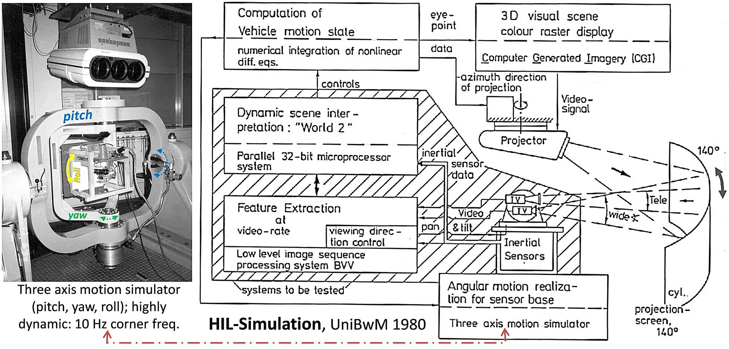
Repeatability is a key element in testing novel systems. Since this cannot be guaranteed for vehicle operation in the real world, the basic approach to machine vision selected by our group was to
- stick to real-time image sequence evaluation (at least about 10 frames per second) and to
- reduce the visual content of the scene artificially such that the frequency requirements could be satisfied using computer hardware available; initially, vector graphics has been used, therefore.
- Typical perturbations from vehicle motion on the real camera system in the closed perception – action loop should be dealt with on all stages of perception.
Therefore, with devices for motion simulation in three rotational degrees of freedom (Drei-Achsen Bewegungs-Simulator, DBS) and for vector graphics (1978), later on for Computer Generated Image sequences (CGI, 1988) on the market, it was decided to install a ‘Hardware-In-the-Loop’ simulation facility for the purpose of developing dynamic vision for motion control on board vehicles. This was probably the first simulation device installed for the purpose of developing full-fledged dynamic machine vision systems; for rocket guidance by infrared sensors they were in wide use in the defense community. Space technology also made use of these rather expensive devices that allow covering a wide spectrum of motion from slow and very precise to high speeds with less precision. Applications to ground-, air-, and space vehicles have been intended at UniBwM right from beginning.
- Taking every second half-frame of the CCIR video signal leads to an evaluation rate of 12.5 Hz or 80 ms per half-frame; initially, this was sufficient for real-time control of standard ground and air vehicles in slow to medium-fast maneuvers.
- High-frequency angular perturbations from the environment on the vehicle and on the measurement devices like cameras and inertial sensors can be generated in the laboratory by a 3-axes motion generator (see figure at left, bottom center).
- A gaze control unit fits on the platform so that active vision under perturbations can be investigated.
- A visual scene of controllable complexity can be generated by separate graphics processors that are fed with the state variables of the numerical simulation. The control variables for the simulation are derived by the visual perception system to be tested (at bottom in top figure). Sensors and visual displays have been replaced with time as technological development provided significant progress in performance:
- The vector graphics system Evans & Sutherland Picture System 2 (1978 – 1988) was the first computer graphics hardware to use 4×4 matrices for homogeneous coordinate transformations; we decided to stick to this framework through the entire vision loop (image sequence generation and interpretation).
- Computer generated images (CGI) became affordable towards the end of the 1980’s; [remember that a decade means an increase in computing power of processors by a factor of 100 or more].
- The DBS has 2 hydraulic outer gimbals (see left) for pitch and yaw with a corner frequency of ~ 10 Hz, and an electrically driven inner axis for roll (bank), which may turn continuously.
- On the inner platform the gaze control system is mounted in a rack simulating vehicle motion.
References
Dickmanns ED, Zapp A, Otto KD (1984). Ein Simulationskreis zur Entwicklung einer automatischen Fahrzeugführung mit bildhaften und inertialen Signalen. In Breitenecker, et al. (ed): Simulationstechnik, Informatik-Fachberichte 85, Springer, pp 554-558
Schiehlen J (1995). Kameraplattformen für aktiv sehende Fahrzeuge. Dissertation, UniBwM, LRT. Kurzfassung
