Aircraft landing by monocular vision in HIL-simulation 1982 to 1987
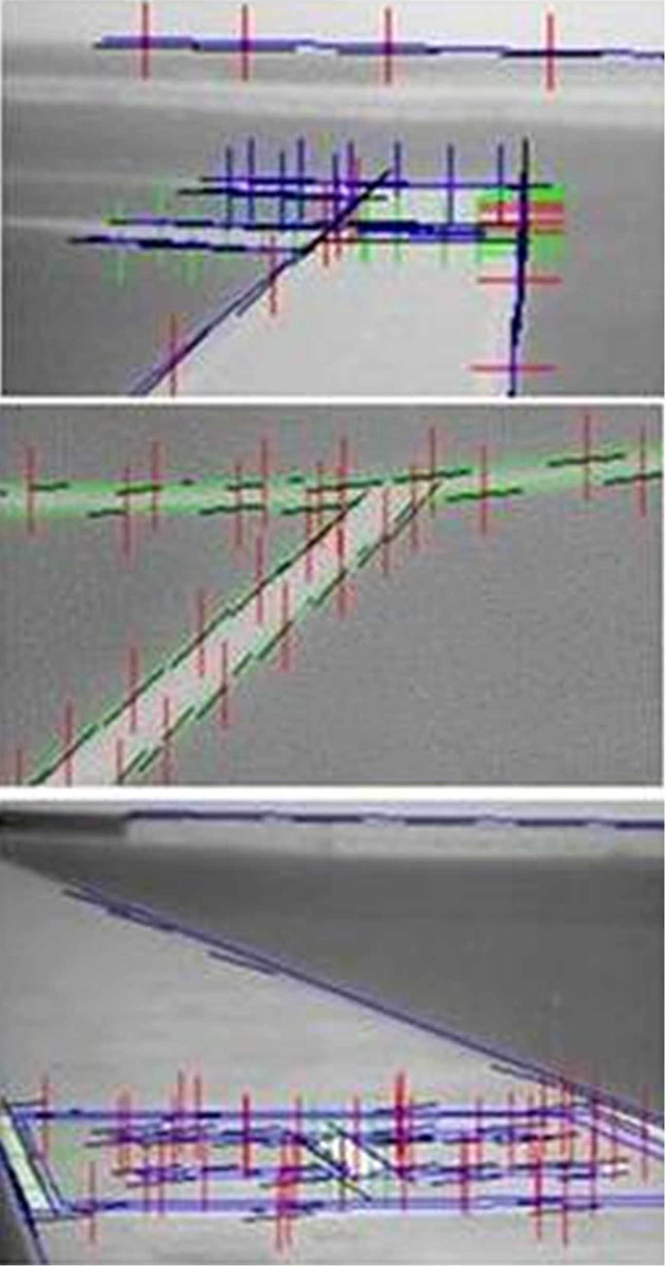
- BVV2 vision system with a few microprocessors Intel 80×86; attention control to predicted regions of interest.
- Vector graphics generating edge pictures of runway and horizon line in correct 3-D perspective projection;
- no inertial sensors, not allowing winds and gusts as unpredictable perturbations.
Aircraft landing with binocular vision and inertial sensors in HIL- simulation 1987 to 1992
- Rotation rates from inertial sensors reduce time delays in perception;
- vision-based perception of runway and horizon;
- lateral ego-state from symmetry of runway image.
- Look-ahead ranges (bi-focal) up to ~ 100 m.
See also A.5 Aircraft landing approach
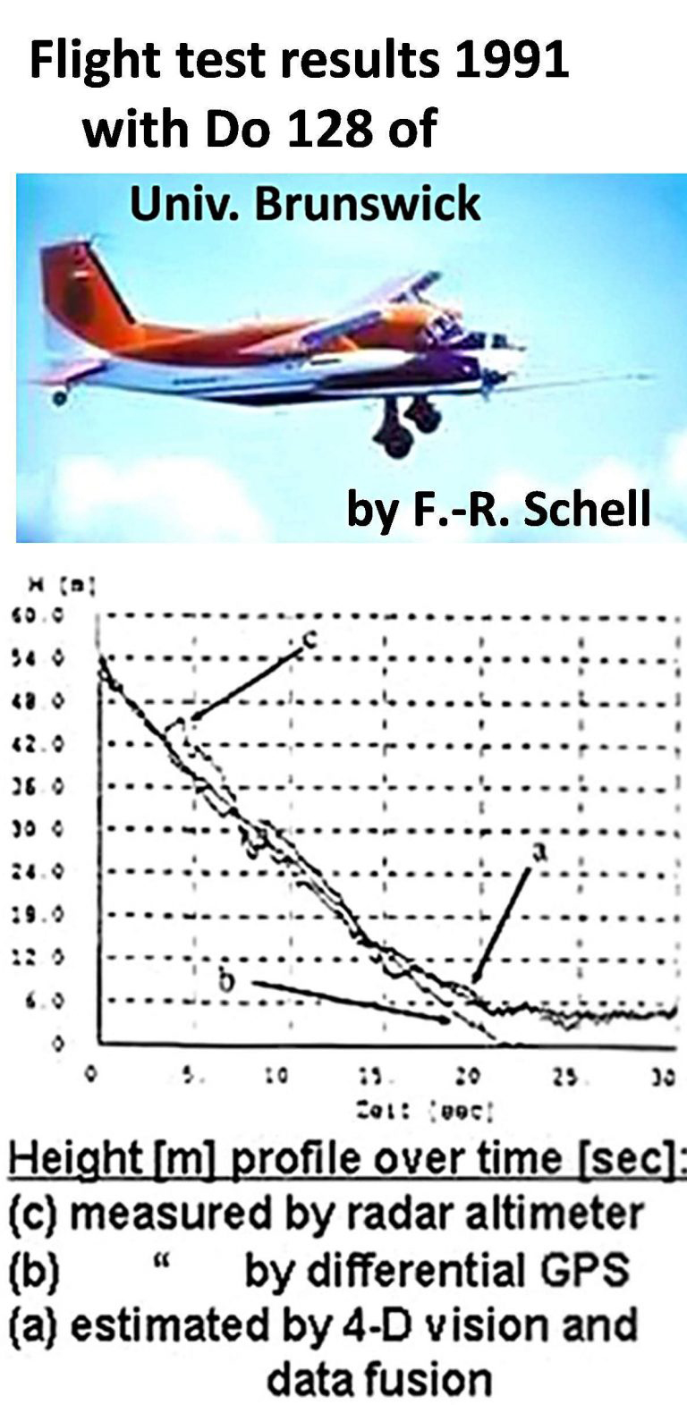
Flight experiments with bi-propeller Do-128 of University of Brunswick 1991
Only the autonomous visual / inertial perception part was tested. A pilot controlled the aircraft for safety reasons till shortly before touch down; then a go-around maneuver followed. The machine vision system also generated control outputs that was compared to the pilot control output after the mission.
(for details see [Schell 1992]).
Helicopter mission performance in HIL- simulation 1992 till 1997
- Transputer system with binocular, gaze controlled vision system
- Mission around simulated Brunswick airport with Computer Generated Image-sequences.
A.6 Helicopters with sense of vision
Video – HelicopterMissionBsHIL-Sim 1997
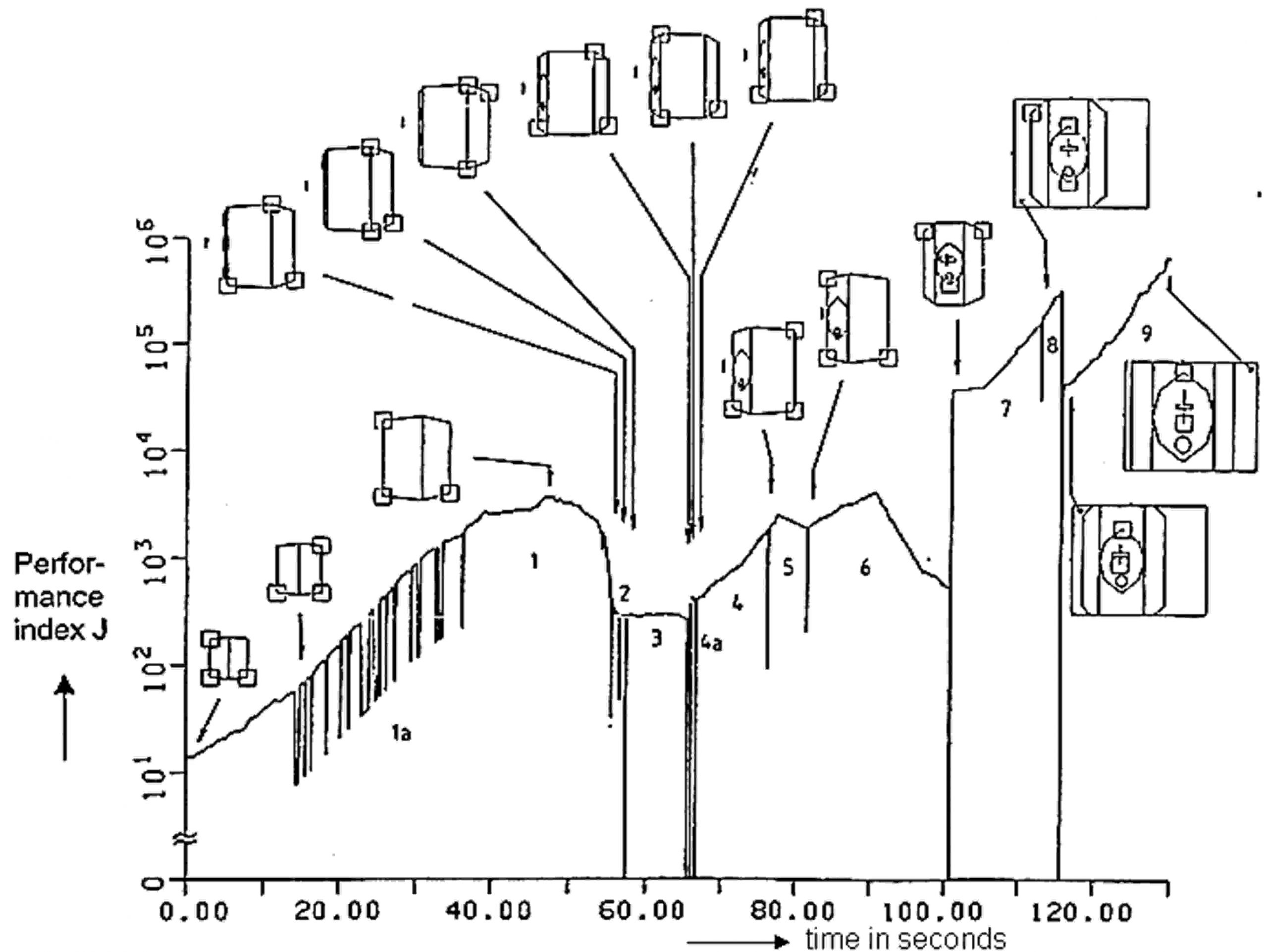
Planar (2-D) visually guided docking by air jet propulsion
in a laboratory setup; the best combination of 4 corner features was to be automatically selected for the approach and docking procedure.
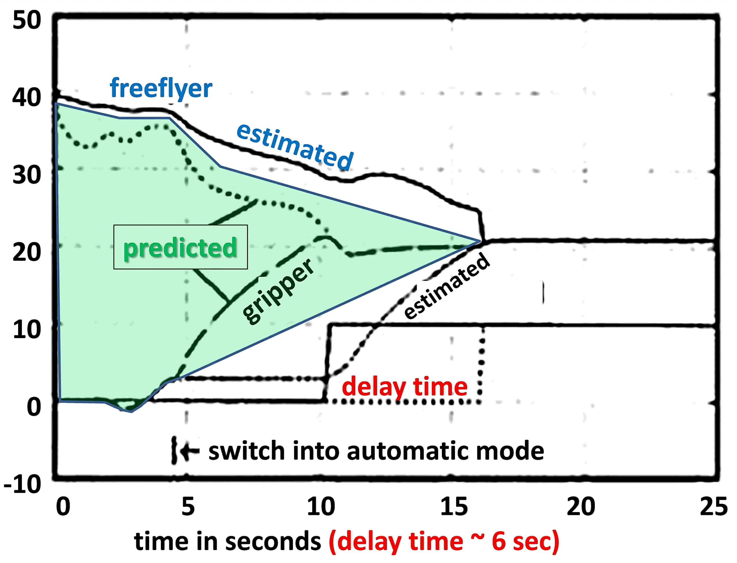
Robot Technology Experiment of DLR-Oberpfaffenhofen in Spacelab D2 onboard Space Shuttle Orbiter ‘Columbia’, May 1993
Remote automatic visual control of grasping a small ‘free-flyer’ with two robot fingers; all computers for data processing were on the ground, resulting in ~ 6 seconds time delay between measurement and action on board.
A.7 Vision – guided grasping in Space
Video – ROTEX- GraspingInSpace 1993


